How to Design Belt Conveyor Drive Pulley to Prevent Misalignment
- There are various causes of belt misalignment, each requiring a different approach.
- Part One: Adjusting the load-bearing idler group
- Part Two: Installation of Self-aligning Idler Groups
- Part Three: Adjusting the Position of the Drive Roller and Idler Roller
- Part Four: Adjustment at the Tensioning Device
- Part Five: The Impact and Adjustment of Material Discharge Position at Transfer Points
- Part Six: Misalignment Adjustment for Bidirectional Conveyors
- Data Source
There are various causes of belt misalignment, each requiring a different approach.
Belt misalignment is the most common fault in belt conveyors. Different causes of misalignment require different methods of rectification. Below are six adjustment methods commonly used on site.
Part One: Adjusting the load-bearing idler group
Applicable scenarios
When the belt misaligns in the middle section of the conveyor, this can be corrected by adjusting the position of the idler group.
Adjustment Principle
During the manufacture of idler groups, the mounting holes on both sides are typically machined as slotted holes to facilitate on-site adjustment.
Specific Operating Procedures
Basic Rule:
If the belt drifts to one side, move the idlers on that side forwards in the direction of belt travel
Or move the idlers on the opposite side backwards
Special cases (belt deviating upwards):
Move the lower idler group to the left
Move the upper idler group to the right
Part Two: Installation of Self-aligning Idler Groups
Types of self-aligning idlers
| Type | Characteristics |
|---|---|
| Central shaft type | Common, simple structure |
| Four-link type | Higher precision |
| Vertical roller type | Corrects misalignment by blocking |
How it works
Self-aligning idlers work by either blocking the idler or allowing it to rotate within a horizontal plane to generate lateral thrust, thereby automatically returning the belt to its centre position.
Recommendations for use
| Condition | Recommended | Reason |
|---|---|---|
| Short-distance conveyor | Yes | Shorter belts are more prone to misalignment and difficult to adjust manually |
| Bidirectional conveyor | Yes | Self-aligning idlers automatically adapt to both directions |
| Long-distance conveyor | No | Self-aligning idlers may have some impact on belt service life |

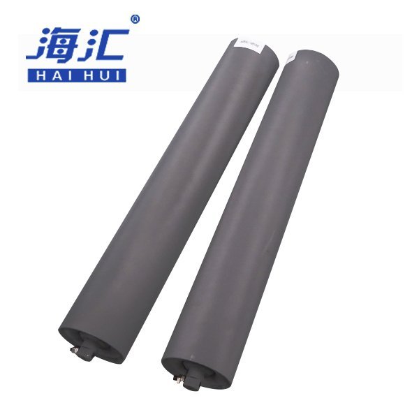
Part Three: Adjusting the Position of the Drive Roller and Idler Roller
Importance
A conveyor belt typically has between two and five rollers. All rollers must be installed perpendicular to the centreline running the length of the conveyor. If the rollers are too far out of alignment, the belt will inevitably run off-centre.
Adjustment Method
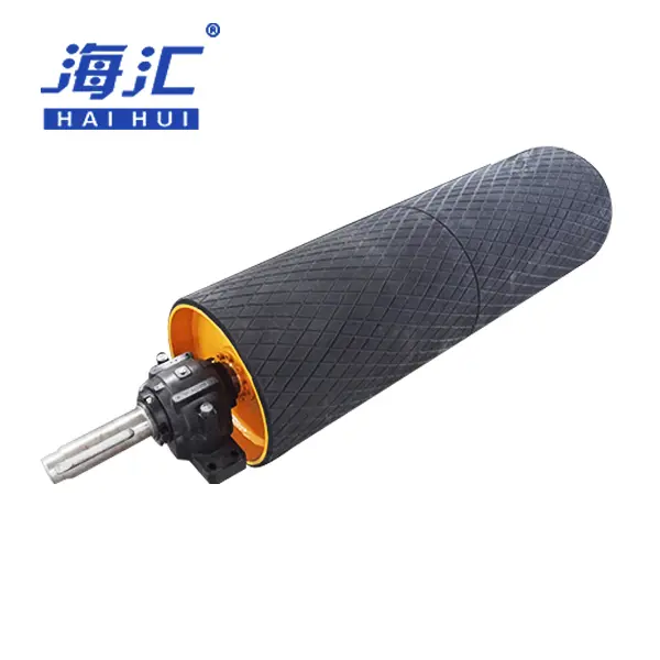
Head roller (drive roller):
| Misalignment Direction | Adjustment Method |
|---|---|
| Belt runs to the right side of the pulley | Move the right bearing housing forward |
| Belt runs to the left side of the pulley | Move the left bearing housing forward |
The procedure can also be carried out in reverse: move the bearing housing on the other side backwards.
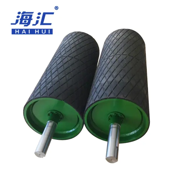
Tail roller (deflection roller):
The method for adjusting the tail roller is the reverse of that for the head roller.
Points to note
Repeated adjustments are required until the belt returns to the correct position.
Ensure the rollers are correctly positioned before making any adjustments.
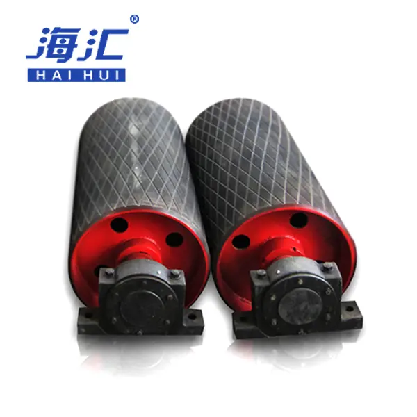
Part Four: Adjustment at the Tensioning Device
Importance
Adjustment at the tensioning point is a crucial step in belt alignment.
Requirements for gravity-tensioned systems
The two deflection rollers above the gravity-tensioning point must not only be perpendicular to the longitudinal direction of the belt but also perpendicular to the line of gravity—that is, the centreline of the roller shaft must be horizontal.
Adjustment requirements for screw or hydraulic tensioning
The two bearing housings of the tensioning drum must be moved simultaneously to ensure that the drum’s axis is perpendicular to the longitudinal direction of the belt.
Adjustment method
The specific adjustment method is similar to that for the idler drums.
Part Five: The Impact and Adjustment of Material Discharge Position at Transfer Points
The Importance of Discharge Position
The discharge position of material at transfer points has a significant impact on belt misalignment. This impact is particularly pronounced when the horizontal projections of the two belt conveyors are perpendicular to one another.
The Impact of Relative Height
| Relative Height | Effect |
|---|---|
| Lower height | Higher horizontal velocity component of material, increasing lateral impact on the lower belt |
| Lower height | Material becomes harder to center, causing material deviation across the belt cross-section |
The relationship between material skew and the direction of deviation
| Material Deviation Direction | Belt Misalignment Direction |
|---|---|
| Material shifts to the right | Belt runs to the left |
| Material shifts to the left | Belt runs to the right |
Design Recommendations
When designing, the relative height between the two belt conveyors should be maximised as far as possible.
Where space is limited, careful consideration should be given to the design and dimensions of components such as the upper and lower hoppers and the feed chutes.
The width of the feed chute should generally be around two-thirds of the belt width.
Baffle plates may be added to block the material flow and alter the direction and position of the material as it falls.
Part Six: Misalignment Adjustment for Bidirectional Conveyors
Difficulty
Adjusting misalignment on bidirectional conveyors is considerably more difficult than on unidirectional conveyors.
Adjustment Procedure
Adjust one direction first; once this direction is correctly aligned, adjust the other direction
During adjustment, carefully observe the relationship between the belt’s direction of movement and the tendency to drift
Adjustments should be carried out one at a time
Key Points for Adjustment
| Priority | Adjustment Area |
|---|---|
| Primary | Drive pulley and bend pulley |
| Secondary | Idler adjustment, material loading point adjustment |
Notes on Jointing
When vulcanising belt joints, ensure that the force is distributed evenly along the length of the belt cross-section
When using a guide chain for traction, the forces on both sides should be as equal as possible
Data Source
Methods for Adjusting Idler Groups — General Industry On-Site Maintenance Experience
Types of Self-Aligning Idlers and Recommendations for Use — Summary of On-Site Maintenance Experience
Drum Adjustment Methods — Industry-Standard Operating Procedures
Requirements for Tensioning Device Adjustment — Belt Conveyor Installation Specifications
Empirical Value for the Width of the Guide Chute at Transfer Points (Approx. 2/3 of Belt Width) — Industry Design Experience
Adjustment Steps for Bidirectional Conveyors — Summary of On-Site Maintenance Experience