Head Pulley on Conveyor: Boost Traction, Cut Downtime, Lower Costs
- Whispers of Head Pulley Mastery
- Key Design Trends in Head Pulley Engineering: Dimensions, Lagging, and Finishes
- Key Steel Grades for Head Pulley Shells
- 4 Steps to Specify a Head Pulley
- Custom vs. Off-the-Shelf Head Pulley Solutions
- Lagging Wear Issues? Ceramic Solutions To The Rescue
- Heavy Conveying: Compliance-Ready Head Pulley Assemblies
- Partner with Haihui for Your Conveyor Drive Solutions
- References
The Head Pulley on a Conveyor Isn’t Just Hardware—It’s the Tipping Point for Tonnage, Tension, and Whether Your Shift Goes Smooth or Sideways
The belt tracks left, the load lags, and suddenly your head pulley on a conveyor is the weak link—slippage, edge wear, and angry production calls stacking up fast. It spins, sure, but traction is what keeps material moving and money in your pocket.
Dial in lagging, shaft fit, and crown geometry or pay with belt damage, motor strain, and re-splicing. A good head pulley survives impact, transfers torque, and keeps the belt tracking true.
Stop letting poor traction eat your throughput. With over 30 years of manufacturing expertise, Haihui offers a 1-day solution proposal (lagging selection, shaft sizing, and price) to fix your drive-end headaches fast. Contact our engineering team today to get started.
Whispers of Head Pulley Mastery
- Traction & Torque Transfer: Optimize lagging type (ceramic, rubber, or grooved), drum diameter, and wrap angle to balance grip, belt tension, and motor efficiency.
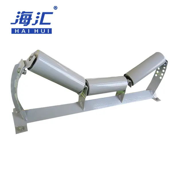
- Belt Tracking & Alignment: Engineer crown geometry or flat-faced precision to keep the belt centered, reducing edge damage and spillage.
- Structural Integrity: Select shell thickness, shaft diameter, and hub fitment to withstand starting torque, impact loads, and cyclic fatigue.
- Maintenance & Safety: Meet CEMA, DIN, and ISO standards; enforce alignment checks, lagging wear inspections, and bearing temperature monitoring for reliable operation.
Key Design Trends in Head Pulley Engineering: Dimensions, Lagging, and Finishes
Smart operations are no longer guessing on head pulley specs; they’re reading the signals in diameter, lagging pattern, shaft fit, and shell finish. From heavy mining belts to aggregate conveyors, shifts in design feel subtle—but they drive uptime and cost-per-ton. Let’s break down what’s really changing.
Emerging Demands in Pulley Diameter and Face Width
In today’s conveyor market, diameter and face width are being tuned to real-world belt speeds and load cycles. The goal? Smarter sizing without compromising torque transfer.
Key drivers include:
- Tighter motor frame limits
- Belt sag and troughing constraints
- Maintenance access for lagging replacement
- Larger diameters reduce belt flex fatigue.
- Wider face widths distribute load better.
- Compact designs fit retrofit scenarios.
Performance Benchmarks in Head Pulley Design
| Pulley Type | Diameter (mm) | Face Width (mm) | Shaft Diameter (mm) | Weight (kg) |
|---|---|---|---|---|
| Light-duty | 315 | 500 | 60 | 85 |
| Medium-duty | 500 | 800 | 80 | 180 |
| Heavy-duty | 630 | 1000 | 100 | 320 |
| Extra-heavy | 800 | 1200 | 120 | 520 |
| Compact | 400 | 600 | 70 | 120 |
Recent data from Martin Engineering’s 2025 conveyor bulletin noted:
“Optimized pulley diameter directly influences belt splice life and energy consumption, becoming a key differentiator in bulk handling systems.”
Brands like Haihui respond by aligning head pulley specs with real conveyor constraints—practical, not flashy.
Forecasting Lagging Patterns and Crown Geometry Trends
The shift in lagging pattern and crown design is subtle but powerful. Modern pulley engineering blends mechanical logic with field-service realities, refining the overall traction and tracking behavior.
Design evolution often follows this path:
- Analyze belt tension and slip margin.
- Select lagging durometer and pattern (plain, grooved, or ceramic tile).
- Refine crown angle (typically 1–2 degrees for flat belts).
- Validate via field torque tests.
Within advanced head pulley systems:
- Structural features
- Ceramic tiles for high-wear zones
- Chevron grooves for water evacuation
- Rubber bonding with vulcanized adhesion
- イノベーション
- Hybrid lagging systems
- Modular tile replacement
- Wear-indicator strips
This is where smart head pulleys separate themselves from average rollers—performance hidden inside robust steel.
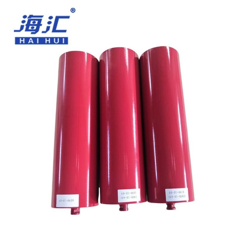
Surface Finish Evolution: From Bare Steel to Protective Coatings
The journey from bare steel to protective coatings reflects changing expectations around surface finish, durability, and corrosion resistance.
Here’s what’s happening:
- Bare steel still signals low-cost convenience.
- Epoxy coatings improve corrosion resistance in wet environments.
- Polyurethane topcoats boost abrasion resistance.
In practical terms:
- Stronger protection against rust
- Longer lagging life
- Better friction consistency
Many premium head pulley solutions now combine layered coatings with precision machining. Haihui integrates heavy-duty protective systems that balance wear resistance and friction—because sharp specs mean nothing if durability falls short.
Head pulleys aren’t just about rotation anymore. It’s about grip, tracking, and staying power.

Key Steel Grades for Head Pulley Shells
Picking steel for head pulley shells is a lot like picking work boots: fit matters, and little details bite later. Get the material mix right, and your pulleys run truer, weld cleaner, and stay safer under shock loads. Haihui keeps head pulley engineering practical by matching steel choices to welding, balancing, and shaft fit needs.
Shell Thickness Ratios Across Popular Grades
For head pulleys, shell thickness isn’t just a gauge call; it’s a dimension and ratio problem tied to each steel grade and the fabrication route.
- Fabrication focus
- Shell rolling: thicker plate needs heavier forming gear.
- Weld prep: bevel angles change with gauge to ensure penetration.
- Service focus
- Impact resistance: thicker shells handle lump damage better.
- Fatigue life: thinner shells flex more, increasing weld stress.
Quick spec snapshot for head pulley ordering (typical shop talk)
| Steel Grade | Nominal Thickness (mm) | Yield Strength (MPa) | Common Use |
|---|---|---|---|
| S235JR | 8 | 235 | Light-duty dry conveyors |
| S355JR | 10 | 355 | General aggregate applications |
| Hardox 400 | 12 | 400 | High-impact mining zones |
| Q345B | 10 | 345 | Heavy-duty port handling |
Carbon-Steel Blends for Superior Weld Integrity
Weld seams fail in boring ways: tiny cracks, porosity, or heat-affected zone softening. So in head pulley fabrication, the carbon-steel blend has to match your welding process and your duty cycle.
- Strength tune-up: a slightly higher carbon grade can hold weld shape, but push it too far and pre-heating becomes mandatory.
- Welding behavior: stable chemistry means less spatter and fewer “mystery” cracks.
Seal reality-checks (keep it simple):
- Dye-penetrant tests should show clean fillets.
- UT scans should stop being a daily headache.
- Balance runs should show minimal vibration.
Haihui usually asks one street-level question: are you chasing speed, or chasing fewer rejects on head pulley shells?
Abrasion-Resistant vs. Structural Steels: Balancing Impact and Cost
When head pulleys need to survive rock drops, abrasion-resistant (AR) steel helps on wear, and structural steel helps calm down cost. The trick is the material choice, because the shell still has to weld to end discs and hubs.
Material choice breaks down like this:
- Wear-target application
- pick AR400/500 where lumps and scrapers are aggressive
- use structural steel where impact is mild and budgets are tight
- Fatigue-target application
- tune resistance via shell thickness, not just grade
- watch weld transitions at hub attachments
Step-by-step “don’t get burned later” flow:
- Confirm lump size and belt speed.
- Pick shell material and thickness.
- Validate with impact tests and finite element analysis.
If your head pulley is for hard-rock mining, this is where Haihui usually pushes testing harder.
Steel Effects on Lagging Adhesion
Bad adhesion doesn’t look dramatic at day one; it shows up as lagging peel, gaps, and angry maintenance calls. In head pulley engineering, the steel grade changes the surface energy, which changes bonding to rubber or ceramic lagging.
What to watch on the material side:
- Mill scale: heavy scale kills primer adhesion.
- Surface roughness: too smooth and the adhesive slides; too rough and you trap voids.
What to lock down on the process side:
- Blast profile: anchor pattern depth should hit spec (typically 75–100 microns).
- Primer window: under-cure looks fine until flexing starts.
Shop-floor checks that actually help:
- Rubber-to-steel peel test after vulcanization.
- Durometer check for lagging hardness.
- Tap test for voids.
4 Steps to Specify a Head Pulley
Haihui keeps the early spec phase simple: lock the drive torque, rough in the shaft geometry, then pull lagging and coatings into real-world service conditions. If you’re specifying a head pulley on a conveyor, these notes help your design stay buildable, shippable, and operationally clean.
Brainstorming Pulley Dimensions: Diameter and Face Width Matrix
Start with a matrix that pairs diameter and face width so dimensions aren’t guessed off vibes; every combo should map to belt width and tension requirements.
| Diameter (mm) | Face Width (mm) | Belt Width Range (mm) | Typical Tension (kN) |
|---|---|---|---|
| 315 | 500 | 400–500 | 30 |
| 500 | 800 | 650–800 | 60 |
| 630 | 1000 | 800–1000 | 100 |
| 800 | 1200 | 1000–1200 | 150 |
| 1000 | 1400 | 1200–1400 | 200 |
Logistics check:
- Pallet layers: confirm footprint doesn’t force wasted truck space.
- Shipping schedule: pick sizes already common in your supplier’s toolset to avoid lead-time drama.
Manufacturing check:
- Tolerance: set go/no-go bands on shell roundness so bearing fits don’t drift.
- Changeover: fewer diameter families means fewer surprises on line.
Rough Layouts Emphasizing Shaft Fit and Hub Connection
Keep the sketch loose, but don’t hand-wave the shaft. The shaft diameter and hub connection decide strength, torque transfer, and how the whole assembly behaves under starting loads.
Quick layout cues: mark the shaft step, then trace the hub contour so it’s readable at a glance.
Fit reality check:
- Keyway size vs. torque rating
- Bearing journal tolerance vs. housing fit
- Locking element clearance vs. shaft deflection
If this is a head pulley on a conveyor, label the “no-weld” zones right on the sketch so the fabricator doesn’t have to guess.
Integrating Lagging Specifications and Groove Patterns
This is where lagging stops being rubber and starts being traction. For a head pulley, your lagging spec needs tight details so grip stays consistent and slip doesn’t wreck the belt from run to run.
Lagging setup:
- Rubber durometer: set a hardness range (60–70 Shore A typical).
- Groove pattern: specify chevron or plain with spacing, depth, and pitch.
- Ceramic tiles: define tile size, shape, and vulcanization method.
Adhesion rules (nested so nothing gets lost):
- Primary bond: rubber-to-steel peel strength (min 6 kN/m).
- Secondary check: tile retention under impact.
Fast checks that save rework:
- Confirm lagging thickness tolerance (typically ±1.5 mm).
- Scan for voids using a rubber tap test.
- Verify cure time and temperature log.
Haihui typically pushes these notes into the drawing file itself, so nobody’s hunting through emails.
Refining Concepts with Shaft Keyway and Bearing Selection
Now tighten the last 10% that causes 90% of headaches. Use shaft keyway specs that match motor torque, then treat bearing selection like a functional requirement, not an afterthought.
Machining + fit decisions:
- Choose key type (square vs. parallel) based on shear load and hub length.
- Map bearing type (spherical roller vs. tapered) to radial and thrust loads.
Bearing rules that save rework:
- Keep quiet zones clean—no weld spatter near journals.
- Avoid over-specifying tolerance classes unless high-speed.
- Confirm lubrication method (grease vs. oil).
If you’re building a head pulley for heavy-duty conveying, this is also where Haihui recommends a quick FEA run before you release the drawing for fabrication.
Custom vs. Off-the-Shelf Head Pulley Solutions
Picking between a custom-engineered head pulley and a standard stock pulley isn’t just vibes; it’s about fit, durability, and how fast you need it. This quick breakdown keeps it real, so you can match performance, price, and uptime without overthinking it.
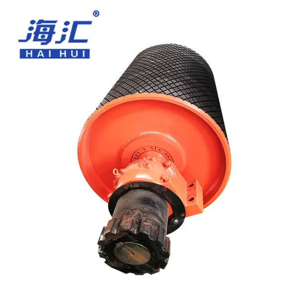
Custom-Engineered Head Pulley
Custom head pulley engineering starts with Design, then gets picky in a good way. It’s the route Haihui pushes when the belt tension, material impact, or uptime story won’t accept “close enough.”
- Bespoke plan, mapped to your conveyor
- Pulley geometry – Unique diameters to clear skirts and chutes; face width and crown tuned for belt width and tracking
- Shaft and hub – Sized for starting torque and overhung load
- Structural reinforcement – End discs and ribs matched to impact zones
- Surface and protection
- Lagging chosen for friction coefficient and wear life
- Coatings aligned to environmental conditions (wet, abrasive, or corrosive)
- Assembly integrity
- Dynamic balancing to reduce bearing stress
- Weld procedure specs to match steel grade
Keyword fit, used in real specs:
- head pulley on conveyor for high-tension mining
- drive pulley with ceramic lagging for wet aggregate
- head pulley for port handling with corrosion protection
Short-tail variations show up in RFQs: head pulley, conveyor head pulley, and head pulley drive—still pointing back to a custom head pulley when approvals get strict.
| Item (example) | Target (mm) | Tolerance (mm) |
|---|---|---|
| Shell diameter | 630 | ±1.0 |
| Face width | 1000 | ±1.5 |
| Shell thickness | 12 | ±0.5 |
| Shaft diameter | 100 | ±0.05 |
| Hub bore | 100 | +0.03/-0.00 |
Stock Head Pulley
A stock head pulley is the “grab it and go” choice: off-the-shelf, ready-made, and usually on a truck fast. If your conveyor is chill about dimensions, standard diameters and standard face widths do the job with less back-and-forth.
- Check fit – Confirm generic shells won’t fight your belt width or bearing housing.
- Pick the look – Stay inside common designs so lagging and coatings are predictable.
- Lock the timeline – Immediate availability cuts lead time, which keeps projects from slipping.
Quick note: many buyers still say “head pulley” when they mean any drive-end pulley; stock pulleys can’t always carry the same performance weight, but they win on speed and cost. Haihui often pairs stock pulleys with smart lagging choices when budgets get tight.
Need a bespoke conveyor component that stands up to heavy loads? Haihui provides comprehensive OEM/ODM customization services, from 3D structural design to full dynamic balancing and lagging application. With flexible MOQs and a responsive engineering team, we deliver physical samples and technical drawings in ~10 days. Explore our customization capabilities today.
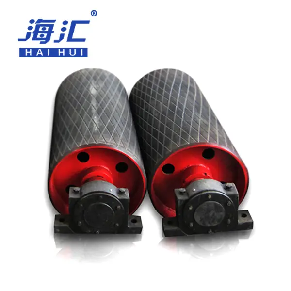
Lagging Wear Issues? Ceramic Solutions To The Rescue
Lagging wear on a head pulley is annoying because it looks like “old stock,” even when the system is new. This cluster keeps it practical: what’s inside ceramic lagging systems, how to pick rubber compounds that stay grippy, and how to prove results with field tests—nice and tidy for Haihui projects.
Anatomy of Ceramic Lagging Systems
For head pulleys, ceramic lagging isn’t magic; it’s layered engineering that slows down abrasion while keeping grip consistent under heavy loads.
Core ingredients (why they matter):
- Ceramic tiles
- Soak up impact energy before rubber takes the hit.
- Work best when matched to adhesive and vulcanization chemical structure.
- Rubber backing
- Interrupts stress transfer after impact sneaks in.
- Helps absorb vibration, so tiles don’t crack.
- Adhesion layer
- Holds tiles and rubber in place; weak bonding means tile loss.
- Decides shear strength vs. peel resistance.
Build details that decide real-life results:
- Tile spacing – Gaps allow rubber flex; too tight and tiles pop under load.
- Tile shape – Hexagonal vs. round affects stress distribution.
- Bonding method – Cold-bond vs. hot-vulcanized; the latter lasts longer in mining.
Selecting Lagging Compounds with High Friction and Wear Resistance
On a head pulley, grip and wear resistance have to play nice together, or you get great traction on a bald shell. Haihui usually treats selection like a quick checklist plus a couple of “don’t mess this up” tests.
Basic picks that save headaches:
- Friction performance – Tied to real coefficient of friction (COF) data (dry and wet).
- Abrasion resistance – Measured by DIN abrasion loss, not just marketing claims.
- Adhesion to shell – Verified by rubber-to-steel peel tests, not just batch sheets.
Fast reality checks (small, cheap, useful):
- Confirm oil and water resistance for dusty/wet conditions.
- Compare durability after scuff and impact—pulleys take hits during loading.
- Validate edge coverage where lagging meets end discs; water ingress starts there.
Quick “watch-outs” (yeah, these bite):
- Rubber that feels great at day 1 can harden or soften under heat—ask for temperature data.
- If you’re sourcing lagging across regions, check cure time and humidity limits so rework doesn’t kill the timeline.
- For head pulleys used in wet environments, don’t accept vague “high-grip” claims—tie it to measurable COF.
Testing Wear Resistance via Field Trials
To prove lagging won’t wash out on the conveyor, shops run accelerated wear trials. You track both material loss and adhesion, because high grip is pointless if the lagging peels.
Test flow used for wear resistance:
- Setup – Choose test standards (common routes include ISO/DIN methods).
- Exposure + checks – Track tonnage handled and inspect for grooving and chunking.
- Pass/fail thinking – Tighten limits for high-tonnage belts; loosen slightly for low-load applications.
| Tonnage (MT) | Rubber Loss (mm) | Tile Retention (%) |
|---|---|---|
| 0 | 0.0 | 100 |
| 500 | 0.5 | 100 |
| 1000 | 1.2 | 99 |
| 2000 | 2.4 | 97 |
| 3000 | 4.0 | 94 |
Reading the numbers without overcomplicating it:
- If loss climbs fast early, suspect soft rubber or high impact angles.
- If tile loss starts while wear is okay, look at bond strength and tile spacing.
Haihui teams often re-run after lagging compound changes, so the “fix” is backed by the same test methods.

Heavy Conveying: Compliance-Ready Head Pulley Assemblies
For head pulleys on a conveyor, the paperwork is only half the battle; the assembly has to behave under real starting torque and shock loads. This cluster walks through CEMA design rules, shaft-fit choices, and inspection habits that keep audits boring (in a good way). Expect practical checks, plain talk, and details that help head pulley assemblies stay safe, legal, and dependable.
CEMA Standards for Shaft and Hub Design
For head pulleys carrying high tension, CEMA compliance isn’t just “use standard parts”; it’s matching shaft diameters and hub fits so nothing fights the torque on a start-up.
Shaft and hub design control points:
- Shaft diameter – Must align with CEMA tables for torque and overhung load.
- Hub fitment – Confirm keyway sizing and locking-element engagement; bad fit causes fretting.
- Bearing selection – Must match radial and thrust loads per CEMA service class.
Transport control points:
- Shaft stress must stay below yield at starting torque (typically 1.5x running).
- Secure hub attachment: keyway tolerance and set-screw torque.
A lot of teams buying head pulley assemblies ask suppliers to pre-align these specs; Haihui commonly supports that matching step so the pulley-and-shaft set ships as a unit, not a guessing game.
Ensuring Structural Safety with Shaft Locking Elements
With head pulleys, the shaft connection is the quiet hero. A locking element blocks slip, stops keyway fretting, and keeps the pulley from wandering after a month of heavy starts.
You’ll usually see taper-lock or shrink-disc systems, and the choice should track the torque, not the trend. High-torque pushes you toward keyless locking devices, while moderate loads tolerate traditional keyways.
Quick shop-floor rules people actually use:
- If the motor is over 100 kW, ask for shrink-disc torque data, not just a catalog number.
- If the spec says CEMA compliant, also ask which service class the design is cleared under.
- If the load is “intermittent,” still verify keyway stress; cycling can be aggressive.
✓ A locking element that survives full torque is nice, but pointless if your maintenance schedule never checks bolt preload.
Inspection Records and QA Logs
Head pulley assemblies get a lot easier to defend when every unit is tied to a clean trail: inspection records plus QA logs.
- Identify – Capture serial number, steel grade, and weld date at fabrication. Link hub, shaft, and lagging batch.
- Record – Store balance results, NDT reports, and shell roundness measurements. Attach storage notes: rust-prevention coating and date.
- Retrieve – Set a “two-click” rule: find any assembly → pull the QA file + inspection records in minutes.
A simple numeric snapshot helps teams spot weak spots fast:
| Control Item | Target Value | Record Example |
|---|---|---|
| Runout (TIR) | ≤ 0.5 mm | Balance log + serial number |
| Weld UT pass rate | 100% | NDT report per assembly |
| Coating thickness | 75–100 µm | Measured per batch |
If you’re sourcing head pulley assemblies at scale, ask the maker how fast they can trace a single unit back to steel coil, shaft blank, and lagging batch; Haihui typically treats that as a baseline, not an add-on.
Partner with Haihui for Your Conveyor Drive Solutions
Stop settling for “close enough.” Operating out of a state-of-the-art 50,000+ m² manufacturing facility, Haihui guarantees precision with 100% NDT inspection and compliance with CEMA, DIN, and ISO 9001 standards. Whether you need heavy-duty mining pulleys or specialized handling drums, we deliver durable, high-performance head pulley assemblies that protect your belt and elevate your throughput.
Ready to build pulleys that perform? We guarantee a response within 12 hours. Request your free technical consultation and get a quote today!
References
- CEMA Standards – cemanet.org
- DIN 22101 – Conveyor belts for bulk material handling
- Martin Engineering 2025 Conveyor Bulletin – martin-eng.com
- Ceramic Lagging Performance Data – flexco.com
- Shaft & Hub Design – skf.com
- Hardox Wear Plate Specifications – ssab.com
- Q345B Steel Properties – chinese-steel.com
- Locking Element Torque Ratings – ringfeder.com
- NDT Testing Methods – ndt.org
- Conveyor Maintenance Best Practices – aggregate.com